DESIGN OF R.C. ONE-WAY SLAB - ACI 318-25
1.0 INPUT DATA
Material Properties (ACI 318-25)
fc' = MPa Specified compressive strength of concrete [ACI
19.2.2]
fy = MPa Specified yield strength of reinforcement [ACI
20.2.2]
γc = kN/m³ Unit weight of concrete
Es = MPa Modulus of elasticity of steel
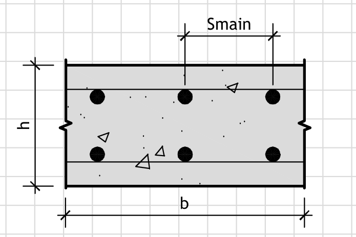
Figure 1: Geometry
RC Slab Dimensions
Load Factors and Strength Reduction Factors
φtension = Strength reduction factor for tension-controlled
sections [ACI 21.2.2]
φshear = Strength reduction factor for shear [ACI 21.2.3]
λ = Modification factor for concrete density [ACI 19.2.4]
Section Dimensions
l =
mm Clear span of slab [ACI 8.7]
h =
mm Overall thickness of slab
b =
mm Width of slab
Loads
qD = kPa Service dead load
qL = kPa Service live load
M =
kN·m Factored moment at midspan
Vu = kN Factored shear at support
Ma = kN·m Service moment for deflection check
Assumed Reinforcement
cc = mm Clear cover to reinforcement [ACI 20.6]
φbar = mm Bar diameter
s =
mm Bar spacing
cagg,max = mm Maximum aggregate size [ACI 26.4.2.1]
2.0 CALCULATIONS
2.1 Design for Flexure
Effective depth
d = h − cc −
φbar/2
d = 150 - 20 - 12/2 = 124.00 mm
Design moment strength
Mn = As·fy·(d
− a/2)
a =
As·fy/(0.85·fc'·b)
Provided reinforcement
As,prov =
b·(φbar/2)²·π/s
As,prov = 1000×(12/2)²×π/150 = 753.98 mm²
ρ = As,prov/(b·d)
ρ = 753.98/(1000×124) = 0.0061
Check minimum reinforcement requirement [ACI 9.6.1.2] - CORRECTED UNITS
ρmin = max(3·√(fc')/fy,
200/fy) Units in psi
ρmin = max(3×√(4352)/60924, 200/60924)
= 0.0018
check_ρmin = OK
(ρ = 0.0061 ≥ ρmin
= 0.0018)
Check maximum reinforcement limit [ACI 9.6.2.1] - UPDATED FOR ACI 318-25
β1 = 0.85 (for f'c ≤ 30 MPa)
For normal-weight concrete [ACI 22.2.2.4.3]
ρb =
0.85·β1·fc'/fy ·
Es/(Es + fy) Balanced
reinforcement ratio
ρb = 0.85×0.85×30/420 ×
200000/(200000+420) = 0.0025
ρmax = 0.85·ρb Maximum
reinforcement for tension-controlled sections
ρmax = 0.85×0.0025 = 0.0021
check_ρmax = OK
(ρ = 0.0061 ≤ ρmax
= 0.0021)
Calculate nominal moment strength
a =
As,prov·fy/(0.85·fc'·b)
a = 753.98×420/(0.85×30×1000) = 12.42 mm
Mn =
As,prov·fy·(d − a/2)
Mn = 753.98×420×(124 - 12.42/2) = 37485528 N·mm
Calculate design moment strength
φMn = φtension·Mn
φMn = 0.9×37485528 = 33736.98 kN·mm = 33.74 kN·m
Check flexural strength
check_flexure = OK
(φMn = 33.74 ≥ M
= 8.85 kN·m)
2.2 Design for Shear - ENHANCED ACI 318-25 PROVISIONS
Shear demand
vu = Vu/(b·d)
vu = 22900/(1000×124) = 0.185 MPa
Concrete shear strength [ACI 318-25 Section 22.5.5.1 - UPDATED]
vc = 0.17·λ·λs·√(fc')·√(1 +
βc) For one-way slab, βc = 0
λs = √(2/(1 + 0.004·d)) Size effect
factor [ACI 22.5.5.1.3]
λs = √(2/(1 + 0.004×124)) = 1.00
vc =
0.17×λ×λs×√(fc')
vc = 0.17×1.0×1.00×√(30) = 0.931 MPa
vc,min = λ·√(fc')
Minimum concrete shear stress [ACI 22.5.5.2]
vc,min = 1.0×√(30) = 5.477 MPa
vc,design = max(vc,
vc,min)
vc,design = max(0.931, 5.477) =
5.477 MPa
Design concrete shear strength
φv·vc,design =
φshear·vc,design
φv·vc,design = 0.75×5.477 = 4.108
MPa
Check shear capacity
check_shear = OK
(vu = 0.185 ≤
φv·vc,design = 4.108 MPa)
2.3 Serviceability - Deflection Check
Effective moment of inertia [ACI 24.2.3.5]
Ie =
min[(Mcr/Ma)³·Ig + [1 −
(Mcr/Ma)³]·Icr,
Ig]
Mcr =
fr·Ig/(yt)
fr = 0.62·λ·√(fc') Modulus of
rupture
fr = 0.62×1.0×√(30) = 3.40 MPa
Ig = b·h³/12
Ig = 1000×150³/12 = 281250000 mm⁴
yt = h/2 Distance from centroid to
extreme tension fiber
yt = 150/2 = 75 mm
Mcr = 3.40×281250000/75 = 12750000 N·mm = 12.75 kN·m
Icr = n·As·(d −
c)² + b·c³/3
c = √[(n·As)² +
2·n·As·d] − n·As
Ec =
4700·√(fc')·√(γc/23.5)
Ec = 4700×√(30)×√(24/23.5) = 25740 MPa
n = Es/Ec
n = 200000/25740 = 7.77
c = √[(7.77×753.98)² + 2×7.77×753.98×124] − 7.77×753.98
= 25.94 mm
Icr = 7.77×753.98×(124-25.94)² +
1000×25.94³/3 = 54468767 mm⁴
Service moment (user-provided for deflection check)
Ma = 6.73 (user input) kN·m
Ie = min((12.75/6.73)³×281250000 +
[1−(12.75/6.73)³]×54468767, 281250000) = 281250000 mm⁴
Deflection calculation (simple span)
Δ = 5·(qD +
qL)·l⁴/(384·Ec·Ie)
Δ = 5×6.4×2900⁴/(384×25740×281250000) = 0.68 mm
Check deflection limits [ACI Table 24.2.2]
Allowable Δ = l/240 = 2900/240 = 12.08 mm
check_deflection = OK
(Δ = 0.68 ≤ Allowable = 12.08 mm)
2.4 Crack Control [ACI 24.3]
Calculate z-factor
z =
β·hc·√(dc·A) [ACI
24.3.2]
β = d/(dc) = 124/(20+12/2) = 4.13
hc = cc + φbar/2
hc = 20 + 12/2 = 26 mm
dc = hc
A = 2·dc·s/number of bars
A = 2×26×150/7 = 1114.29 mm²
z = 4.13×26×√(26×1114.29) = 15680 N/mm
check_crack = OK
(z = 15680 ≤ 30000 N/mm for interior exposure)
2.5 Bar Spacing Requirements [ACI 25.2]
Minimum spacing requirements [ACI 25.2.1]
smin = max(φbar,
1.33·cagg,max, 25 mm)
smin = max(12, 1.33×19, 25) = 25.00 mm
check_smin = OK
(s = 150 ≥ smin =
25.00 mm)
Maximum spacing for crack control [ACI 24.3.2]
smax,crack = 300 mm
For interior exposure with moderate corrosion risk
check_smax,crack = OK
(s = 150 ≤
smax,crack = 300 mm)
Maximum spacing for temperature and shrinkage [ACI 24.4.3]
smax,temp = min(5·h, 450 mm)
smax,temp = min(5×150, 450) = 450.00 mm
check_smax,temp = OK
(s = 150 ≤
smax,temp = 450.00 mm)
Spacing check summary
check_spacing = OK
(All spacing requirements satisfied)
*** OUTPUT SUMMARY ***
Design Results
Effective depth, d = 124.00
mm
Provided reinforcement, As,prov = 753.98 mm²
Reinforcement ratio, ρ = 0.0061
Design moment strength, φMn = 33.74 kN·m
Flexural strength check: OK
Shear stress, vu = 0.185 MPa
Design concrete shear strength, φv·vc,design =
4.108 MPa
Shear capacity check: OK
Calculated deflection, Δ = 0.68
mm
Allowable deflection = 12.08
mm
Deflection check: OK
Crack control check: OK
Bar spacing check: OK
RESULTS
ALL CHECKS PASSED - DESIGN IS ADEQUATE (ACI 318-25 COMPLIANT)