RHS DESIGN CALCULATOR
Design according to AISC 360-22
Method = Select design methodology
Member Geometry (RHS-Section)
L = ft Member Length
b = in Section Width (Outer)
h = in Section Height (Outer)
t = in Wall Thickness
Figure 1: Geometry
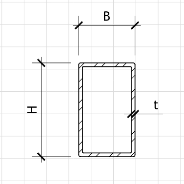
RHS-Section Dimensions
Material Properties (ASTM A500 Grade C)
E = ksi Elastic Modulus
Fy = ksi Yield Strength
Fu = ksi Ultimate Tensile Strength
Axial Loads (Tension Positive, Compression Negative)
ND = kips Dead Load Axial Force
NL = kips Live Load Axial Force
Bending Loads
wD = klf Dead Load (Uniformly Distributed)
wL = klf Live Load (Uniformly Distributed)
PD = kips Dead Load (Point Load at Midspan)
PL = kips Live Load (Point Load at Midspan)
End Restraints
Kx = Effective Length Factor (x-axis)
Ky = Effective Length Factor (y-axis)
Kz = Effective Length Factor (torsional)
LRFD Load Factors:
wu = 1.2·wD + 1.6·wL = 2.60 klf Factored Distributed Load
Pu = 1.2·PD + 1.6·PL = 44.00 kips Factored Point Load
Nu = 1.2·ND + 1.6·NL = 0.00 kips Factored Axial Force
ASD Load Factors:
wa = wD + wL = 1.50 klf Allowable Distributed Load
Pa = PD + PL = 30.00 kips Allowable Point Load
Na = ND + NL = 0.00 kips Allowable Axial Force
Mmax = w·L²/8 + P·L/4 = 136.25 kip-ft Maximum Design Moment
Vmax = w·L/2 + P/2 = 30.50 kips Maximum Design Shear
bi = b − 2·t = 7 in Inner Width
hi = h − 2·t = 11 in Inner Height
Ag = b·h − bi·hi = 12.25 in² Gross Area
Ix = 269.4 in⁴ Second Moment of Area (strong axis)
Iy = 131.5 in⁴ Second Moment of Area (weak axis)
Sx = 44.9 in³ Elastic Section Modulus (x-axis)
Sy = 32.9 in³ Elastic Section Modulus (y-axis)
Zx = 57.3 in³ Plastic Section Modulus (x-axis)
rx = 4.69 in Radius of gyration (x-axis)
ry = 3.28 in Radius of gyration (y-axis)
J = 455.1 in⁴ Torsional Constant
Tension Strength (Chapter D)
Ag = 12.25 in²
Pn = Fy·Ag = 612.5 kips Nominal Tension Capacity
φt = 0.90 Resistance Factor (LRFD)
φtPn = 551.3 kips Design Tension Strength (LRFD)
Pn/Ωt = 366.8 kips Allowable Tension Strength (ASD)
Tension Check: Tensionratio = |N|·φtPn−1 = 0.000
Compression Strength (Chapter E)
Lc,x = Kx·L·12 = 240 in Effective Length (x-axis)
Lc,y = Ky·L·12 = 240 in Effective Length (y-axis)
Lc,z = Kz·L·12 = 240 in Effective Length (torsional)
rmin = min(rx, ry) = 3.28 in Minimum Radius of Gyration
λ = Lc/rmin = 73.2 Slenderness Parameter
Fe = π²·E/λ² = 5.35 ksi Euler Buckling Stress
Fcr = 0.877·Fe = 4.69 ksi Critical Buckling Stress
Pn = Fcr·Ag = 57.5 kips Nominal Compression Capacity
φcPn = 51.8 kips Design Compression Strength (LRFD)
Pn/Ωc = 34.4 kips Allowable Compression Strength (ASD)
Compression Check: Compressionratio = |N|·φcPn−1 = 0.000
Bending Strength (Chapter F)
Mn,x = Fy·Zx = 238.8 kip-ft Nominal Moment Capacity (x-axis)
φb = 0.90 Resistance Factor (LRFD)
φbMn,x = 179.1 kip-ft Design Moment Strength (LRFD)
Bending Check: Bendingratio = Mmax/(φbMn,x) = 0.761
Combined Axial and Bending (Chapter H)
Pu/(φcPn) = 0.000
Mu/(φbMn) = 0.761
Interaction Check: Interactionratio = Pu/(φcPn) + Mu/(φbMn) = 0.761
Shear Strength (Chapter G)
Av,x = 2·(h−2·t)·t = 11.00 in² Shear Area (x-axis)
Vn,x = 0.6·Fy·Av,x = 330.0 kips Nominal Shear Strength (x-axis)
φvVn,x = 297.0 kips Design Shear Strength (LRFD)
Shear Check: Shearratio = Vmax/(φvVn,x) = 0.103
Deflection Check (Serviceability)
δmax = 5·wL·L⁴/(384·E·Ix) + PL·L³/(48·E·Ix) = 0.78 in
δlimit = L/360 = 0.67 in
Deflection Check: Deflectionratio = δmax/δlimit = 1.16
Compact Section Check (AISC Section B4)
λp = 0.38·√(E/Fy) = 10.8 Limiting λ for compact flange
λf = (b/t) = 16.00 Flange slenderness
λpw = 2.42·√(E/Fy) = 68.9 Limiting λ for compact web
λw = (h−2·t)/t = 22.00 Web slenderness
Section Classification: Compact