ANGLE SECTION DESIGN CALCULATOR
Design according to EN1993-1-1
Method = Select design approach per EN 1990
Member Geometry (Equal Angle Section)
L = m Member Length
b = mm Leg Length
t = mm Leg Thickness
Figure 1: Geometry
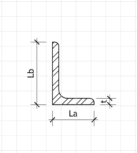
L-Section Dimensions
Material Properties (EN 10025-2 S275)
E = MPa Elastic Modulus
fy = MPa Yield Strength
fu = MPa Ultimate Tensile Strength
Actions (kN, kN/m)
Gk = kN/m Permanent Actions (Dead Load)
Qk,1 = kN/m Variable Actions (Live Load)
NG = kN Permanent Axial Force
NQ = kN Variable Axial Force
Partial Factors (EN 1990)
γG = Partial Factor for Permanent Actions
γQ = Partial Factor for Variable Actions
Imperfections and Buckling
α = Imperfection Factor (Table 6.1 - Angles)
Ku = Effective Length Factor (uncased)
Kc = Effective Length Factor (cased)
Ed = 1.35·Gk + 1.50·Qk,1 = 18.75 kN/m Design Value of Distributed Load
NEd = 1.35·NG + 1.50·NQ = 67.50 kN Design Value of Axial Force
MEd = Ed·L²/8 = 21.09 kN·m Design Value of Maximum Moment
VEd = Ed·L/2 = 28.13 kN Design Value of Maximum Shear
A = 2·b·t − t² = 19.00 cm² Cross-sectional Area
Iu = 271.30 cm⁴ Second Moment of Area (u-axis, major)
Iv = 63.58 cm⁴ Second Moment of Area (v-axis, minor)
Iz = 95.00 cm⁴ Second Moment of Area (z-axis, about centroid)
Wel,min = 25.71 cm³ Minimum Elastic Section Modulus
iu = 3.78 cm Radius of gyration (u-axis)
iv = 1.83 cm Radius of gyration (v-axis)
rmin = 1.83 cm Minimum radius of gyration
ez = 3.70 cm Distance from centroid to back of leg
Tension Resistance (Clause 6.2.3)
Npl,Rd = A·fy/γM0 = 522.50 kN Design Plastic Resistance in Tension
Nu,Rd = 0.6·A·fu/γM2 = 492.96 kN Design Resistance for Net Section
Tension Check: NEd/Npl,Rd = 0.129
Compression Resistance (Clause 6.2.4)
Minor Axis Buckling (v-axis):
Lc,v = Ku·L·100 = 300.0 mm Effective length (minor axis)
λ̄v = Lc,v/(iv·π)·√(fy/E) = 1.00
χv = 0.63 Reduction factor (v-axis)
Nb,Rd,v = χv·A·fy/γM1 = 329.18 kN Buckling resistance (v-axis)
Major Axis Buckling (u-axis):
Lc,u = Ku·L·100 = 300.0 mm Effective length (major axis)
λ̄u = Lc,u/(iu·π)·√(fy/E) = 0.48
χu = 0.89 Reduction factor (u-axis)
Nb,Rd,u = χu·A·fy/γM1 = 465.03 kN Buckling resistance (u-axis)
Critical Axis: v-axis (minor)
Compression Check: NEd/Nb,Rd = 0.205
Bending Resistance (Clause 6.2.5)
Mc,Rd = Wel,min·fy/γM0 = 70.70 kN·m Design Moment Resistance
Bending Check: MEd/Mc,Rd = 0.298
Combined Axial and Bending (Clause 6.2.9)
For angles with bending about minor axis and axial compression:
km = 0.49 Moment modification factor
δmod = 0.85 Modification factor
Interaction Check: NEd/Nb,Rd + km·MEd/(δmod·Mc,Rd) = 0.389
Shear Resistance (Clause 6.2.6)
Av = A/2 = 9.50 cm² Shear Area
Vpl,Rd = Av·fy/(√3·γM0) = 151.11 kN Design Shear Resistance
Shear Check: VEd/Vpl,Rd = 0.186
Local Buckling Check (Clause 6.2.3.2)
b/t = b/t = 10.00 Leg slenderness ratio
ε = √(235/fy) = 0.92 Material coefficient
Class 1 limit = 9·ε = 8.31 Class 1 limit
Class 2 limit = 10·ε = 9.23 Class 2 limit
Class 3 limit = 14·ε = 12.93 Class 3 limit
Section Classification: Class 2
Deflection Check (Serviceability)
δmax = 5·Gk·L⁴/(384·E·Iu) = 4.25 mm
δlimit = L/250 = 12.00 mm
Deflection Check: δmax/δlimit = 0.354