I-BEAM DESIGN CALCULATOR
Design according to EN1993-1-1
Method = Select design approach per EN 1990
Member Geometry (I-Section)
L = m Member Length
h = mm Section Depth
b = mm Flange Width
tf = mm Flange Thickness
tw = mm Web Thickness
Figure 1: Geometry
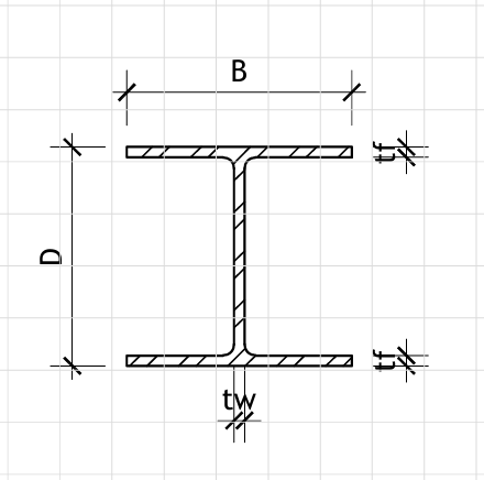
I-Section Dimensions
Material Properties (EN 10025-2 S275)
E = MPa Elastic Modulus
fy = MPa Yield Strength
fu = MPa Ultimate Tensile Strength
Actions (kN, kN/m)
Gk = kN/m Permanent Actions (Dead Load)
Qk,1 = kN/m Variable Actions (Live Load)
NG = kN Permanent Axial Force
NQ = kN Variable Axial Force
Partial Factors (EN 1990)
γG = Partial Factor for Permanent Actions
γQ = Partial Factor for Variable Actions
Imperfections
α = Imperfection Factor (EN 1993-1-1 Table 6.1)
K = Effective Length Factor
Ed = 1.35·Gk + 1.50·Qk,1 = 52.75 kN/m Design Value of Distributed Load
NEd = 1.35·NG + 1.50·NQ = 192.50 kN Design Value of Axial Force
MEd = Ed·L²/8 = 237.38 kN·m Design Value of Maximum Moment
VEd = Ed·L/2 = 158.25 kN Design Value of Maximum Shear
hw = h − 2·tf = 276 mm
A = 2·b·tf + hw·tw = 62.88 cm² Cross-sectional Area
Iy = 8333.33 cm⁴ Second Moment of Area (strong axis)
Iz = 320.00 cm⁴ Second Moment of Area (weak axis)
Wel,y = 555.56 cm³ Elastic Section Modulus (strong axis)
Wpl,y = 622.22 cm³ Plastic Section Modulus (strong axis)
iy = 11.51 cm Radius of gyration (strong axis)
iz = 2.26 cm Radius of gyration (weak axis)
Tension Resistance (Clause 6.2.3)
Npl,Rd = A·fy/γM0 = 1729.20 kN Design Plastic Resistance in Tension
Nu,Rd = 0.6·Anet·fu/γM2 = 1621.75 kN Design Resistance for Net Section
Tension Check: NEd/Npl,Rd = 0.111
Compression Resistance (Clause 6.2.4)
λ̄ = L/(i·π)·√(fy/E) = 0.83 Normalized slenderness
χ = 1/(Φ + √(Φ² − λ̄²)) = 0.74 Reduction factor
Φ = 0.5·[1 + α(λ̄ − 0.2) + λ̄²] = 0.93 Initial imperfection factor
Nb,Rd = χ·A·fy/γM1 = 1279.56 kN Design Buckling Resistance
Compression Check: NEd/Nb,Rd = 0.151
Bending Resistance (Clause 6.2.5)
Mc,Rd = Wpl,y·fy/γM0 = 1711.11 kN·m Design Moment Resistance
Bending Check: MEd/Mc,Rd = 0.139
Combined Axial and Bending (Clause 6.2.9)
MN,Rd = Mc,Rd·(1 − NEd/Npl,Rd) = 1519.89 kN·m Reduced Moment Resistance
Interaction Check: NEd/Nb,Rd + MEd/MN,Rd = 0.285
Shear Resistance (Clause 6.2.6)
Av = h·tw = 24.00 cm² Shear Area
Vpl,Rd = Av·fy/(√3·γM0) = 382.92 kN Design Shear Resistance
Shear Check: VEd/Vpl,Rd = 0.413
Deflection Check (Serviceability)
δmax = 5·Gk·L⁴/(384·E·Iy) = 8.52 mm
δlimit = L/250 = 24.00 mm
Deflection Check: δmax/δlimit = 0.355
Section Classification (EN 1993-1-1 Table 5.2)
c/tf = (b − tw)/(2·tf) = 8.00 Flange slenderness ratio
ε = √(235/fy) = 0.92 Material coefficient
Class 1 limit = 9·ε = 8.31 Class 1 flange limit
Class 2 limit = 10·ε = 9.23 Class 2 flange limit
Section Classification: Class 1