RHS DESIGN CALCULATOR
Design according to EN1993-1-1
Method = Select design approach per EN 1990
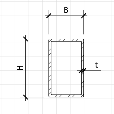
Member Geometry (Rectangular Hollow Section)
L = m Member Length
h = mm Section Height (Outer)
b = mm Section Width (Outer)
t = mm Wall Thickness
Figure 1: Geometry
RHS-Section Dimensions
Material Properties (EN 10210 S355)
E = MPa Elastic Modulus
fy = MPa Yield Strength
fu = MPa Ultimate Tensile Strength
Actions (kN, kN/m)
Gk = kN/m Permanent Actions (Dead Load)
Qk,1 = kN/m Variable Actions (Live Load)
NG = kN Permanent Axial Force
NQ = kN Variable Axial Force
Partial Factors (EN 1990)
γG = Partial Factor for Permanent Actions
γQ = Partial Factor for Variable Actions
Imperfections and Buckling
α = Imperfection Factor (Table 6.1 - RHS)
Ky = Effective Length Factor (y-y axis)
Kz = Effective Length Factor (z-z axis)
Ed = 1.35·Gk + 1.50·Qk,1 = 69.50 kN/m Design Value of Distributed Load
NEd = 1.35·NG + 1.50·NQ = 306.00 kN Design Value of Axial Force
MEd,y = Ed·L²/8 = 313.13 kN·m Design Moment (Strong Axis)
MEd,z = kN·m Design Moment (Weak Axis)
VEd = Ed·L/2 = 208.50 kN Design Value of Maximum Shear
hi = h − 2·t = 184 mm Inner Height
bi = b − 2·t = 84 mm Inner Width
A = 2·t·(h + b − 2·t) = 43.52 cm² Cross-sectional Area
Iy = 2591.25 cm⁴ Second Moment of Area (strong axis)
Iz = 959.58 cm⁴ Second Moment of Area (weak axis)
Wel,y = 259.13 cm³ Elastic Section Modulus (strong axis)
Wel,z = 191.92 cm³ Elastic Section Modulus (weak axis)
Wpl,y = 325.00 cm³ Plastic Section Modulus (strong axis)
Wpl,z = 250.00 cm³ Plastic Section Modulus (weak axis)
iy = 7.72 cm Radius of gyration (strong axis)
iz = 4.69 cm Radius of gyration (weak axis)
Tension Resistance (Clause 6.2.3)
Npl,Rd = A·fy/γM0 = 1544.96 kN Design Plastic Resistance in Tension
Nu,Rd = 0.6·A·fu/γM2 = 1065.38 kN Design Resistance for Net Section
Tension Check: NEd/Npl,Rd = 0.198
Compression Resistance (Clause 6.2.4)
Strong Axis (y-y):
λ̄y = Ky·L/(iy·π)·√(fy/E) = 0.88
χy = 0.71 Reduction factor (y-y)
Nb,Rd,y = χy·A·fy/γM1 = 1096.92 kN Buckling resistance (y-y)
Weak Axis (z-z):
λ̄z = Kz·L/(iz·π)·√(fy/E) = 0.59
χz = 0.84 Reduction factor (z-z)
Nb,Rd,z = χz·A·fy/γM1 = 1297.77 kN Buckling resistance (z-z)
Critical Axis: y-y axis
Compression Check: NEd/Nb,Rd = 0.279
Bending Resistance (Clause 6.2.5)
Strong Axis (y-y):
Mc,Rd,y = Wpl,y·fy/γM0 = 1153.75 kN·m Design moment resistance (y-y)
Weak Axis (z-z):
Mc,Rd,z = Wpl,z·fy/γM0 = 887.50 kN·m Design moment resistance (z-z)
Bending Check (y-y): MEd,y/Mc,Rd,y = 0.271
Combined Axial and Bending (Clause 6.2.9)
MN,y,Rd = Mc,Rd,y·(1 − NEd/Npl,Rd) = 924.69 kN·m Reduced moment resistance (y-y)
MN,z,Rd = Mc,Rd,z·(1 − NEd/Npl,Rd) = 711.98 kN·m Reduced moment resistance (z-z)
Interaction Check: NEd/Nb,Rd + MEd,y/MN,y,Rd = 0.617
Shear Resistance (Clause 6.2.6)
Av = 2·h·t/√3 = 18.48 cm² Shear Area
Vpl,Rd = Av·fy/γM0 = 656.04 kN Design Shear Resistance
Shear Check: VEd/Vpl,Rd = 0.318
Local Buckling Check (Clause 6.2.3.2)
c/t = (h − 2·t)/t = 23.00 Web slenderness ratio
ε = √(235/fy) = 0.81 Material coefficient
Class 1 limit = 33·ε = 26.73 Class 1 limit
Class 2 limit = 38·ε = 30.78 Class 2 limit
Class 3 limit = 42·ε = 34.02 Class 3 limit
Section Classification: Class 1
Deflection Check (Serviceability)
δmax = 5·Gk·L⁴/(384·E·Iy) = 14.85 mm
δlimit = L/250 = 24.00 mm
Deflection Check: δmax/δlimit = 0.619