DESIGN OF R.C. CORBEL
Design according to HK CoP 2013
Material Properties
fcu = MPa Characteristic concrete cube strength
fy = MPa Characteristic steel yield strength
Column Properties
bc = mm Column dimension in X-direction
hc = mm Column dimension in Y-direction
cc = mm Concrete cover
N = kN Minimum axial load (compression +ve)
Figure 1: Typical Beam-Column Joint Configuration
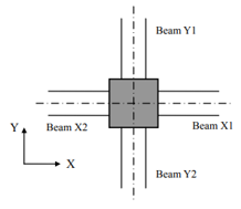
Input "0" for all parameters if beam is NOT present on that side
For beam type: Input "1" = Wind/Seismic beam, "0" = Gravity only
BX1 = Beam type (1=W/S, 0=Gravity)
bx1 = mm Breadth
hx1 = mm Overall depth
dx1 = mm Effective depth
Ast,x1 = mm² Top steel (hogging)
Asb,x1 = mm² Bottom steel (sagging)
BX2 = Beam type (1=W/S, 0=Gravity)
bx2 = mm Breadth
hx2 = mm Overall depth
dx2 = mm Effective depth
Ast,x2 = mm² Top steel (hogging)
Asb,x2 = mm² Bottom steel (sagging)
BY1 = Beam type (1=W/S, 0=Gravity)
by1 = mm Breadth
hy1 = mm Overall depth
dy1 = mm Effective depth
Ast,y1 = mm² Top steel (hogging)
Asb,y1 = mm² Bottom steel (sagging)
BY2 = Beam type (1=W/S, 0=Gravity)
by2 = mm Breadth
hy2 = mm Overall depth
dy2 = mm Effective depth
Ast,y2 = mm² Top steel (hogging)
Asb,y2 = mm² Bottom steel (sagging)
X-Direction
Mh,x1 = kNm Hogging at X1
Ms,x1 = kNm Sagging at X1
Mh,x2 = kNm Hogging at X2
Ms,x2 = kNm Sagging at X2
Y-Direction
Mh,y1 = kNm Hogging at Y1
Ms,y1 = kNm Sagging at Y1
Mh,y2 = kNm Hogging at Y2
Ms,y2 = kNm Sagging at Y2
Horizontal Joint Shear Reinforcement
Horizontal joint shear reinforcement shall consist of links or hoops uniformly distributed between but not immediately adjacent to the innermost layers of the top and bottom beam reinforcement.
db,h = mm Diameter
Sh = mm Vertical spacing (≤ min[10db; 200mm])
Vertical Joint Shear Reinforcement
Vertical joint shear reinforcement should consist of vertical links or intermediate column bars adequately anchored in the column and placed between the corner bars and within the effective joint area. Each vertical face of the joint should be provided with at least one vertical joint shear bar.
db,v = mm Diameter
Sv = mm Horizontal spacing (≤ max[0.25X; 200mm])
Case 1: Non sway / gravity frame | Case 2: Sway frame, gravity dominant | Case 3: Sway frame, lateral dominant
X-direction:
Y-direction:
X-direction:
Y-direction:
X-direction:
Y-direction:
Effective joint widths:
Nominal shear stresses:
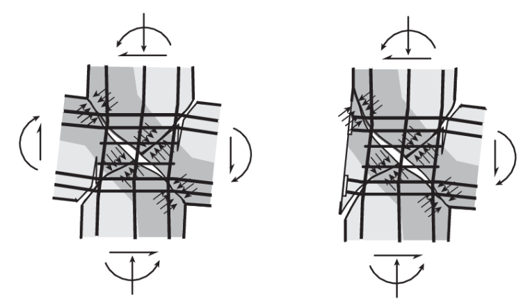
Figure 2: Typical Joint Shear Failure
X-direction:
Horizontal reinforcement provided:
Vertical reinforcement required (X-direction):
Y-direction:
Horizontal reinforcement provided:
Vertical reinforcement required (Y-direction):
Gross area, Ag = 218750 mm²
Case X: 3 - Sway, Lateral Dominant
Case Y: 2 - Sway, Gravity Dominant
Joint shear forces:
Vjhx = 2590.00 kN
Vjhy = 934.47 kN
Nominal shear stresses:
vjhx = 11.82 MPa
vjhy = 1.71 MPa
vlimit = 9.00 MPa
Shear stress check X: FAIL
Shear stress check Y: PASS
X-direction reinforcement:
Horizontal: 7 sets T16-4legs = 1407.43 mm²
Vertical: — sets T20-—legs = 0 mm²
Y-direction reinforcement:
Horizontal: 5 sets T16-3legs = 603.19 mm²
Vertical: 8 sets T20-2legs = 1256.64 mm²