ANGLE DESIGN CALCULATOR
Design according to AISC 360-22
Method = Select design methodology
Member Geometry (Angle-Section)
L = ft Member Length
b1 = in First Leg Width
b2 = in Second Leg Width
t = in Leg Thickness
Figure 1: Geometry
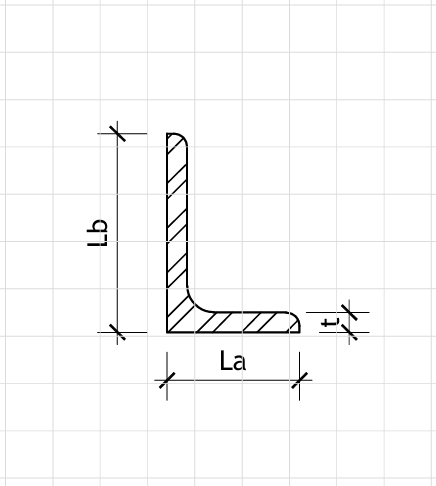
L-Section Dimensions
Material Properties (ASTM A36)
E = ksi Elastic Modulus
Fy = ksi Yield Strength
Fu = ksi Ultimate Tensile Strength
Axial Loads (Tension Positive, Compression Negative)
ND = kips Dead Load Axial Force
NL = kips Live Load Axial Force
Bending Loads
wD = klf Dead Load (Uniformly Distributed)
wL = klf Live Load (Uniformly Distributed)
PD = kips Dead Load (Point Load at Midspan)
PL = kips Live Load (Point Load at Midspan)
End Restraints
Kmin = Effective Length Factor (Minimum)
LRFD Load Factors:
wu = 1.2·wD + 1.6·wL = 1.56 klf Factored Distributed Load
Pu = 1.2·PD + 1.6·PL = 22.00 kips Factored Point Load
Nu = 1.2·ND + 1.6·NL = 0.00 kips Factored Axial Force
ASD Load Factors:
wa = wD + wL = 0.90 klf Allowable Distributed Load
Pa = PD + PL = 15.00 kips Allowable Point Load
Na = ND + NL = 0.00 kips Allowable Axial Force
Mmax = w·L²/8 + P·L/4 = 50.25 kip-ft Maximum Design Moment
Vmax = w·L/2 + P/2 = 11.25 kips Maximum Design Shear
Ag = b1·t + b2·t − t² = 4.75 in² Gross Area
Ix = 21.8 in⁴ Second Moment of Area (x-axis through centroid)
Iy = 12.5 in⁴ Second Moment of Area (y-axis through centroid)
Ixy = 15.3 in⁴ Product of Inertia
Imax = 31.2 in⁴ Maximum Principal Moment of Inertia
Imin = 3.1 in⁴ Minimum Principal Moment of Inertia
θp = 32.5 deg Principal Axis Angle
Sx = 6.2 in³ Elastic Section Modulus (x-axis)
Sy = 4.3 in³ Elastic Section Modulus (y-axis)
rx = 2.14 in Radius of gyration (x-axis)
ry = 1.62 in Radius of gyration (y-axis)
rmin = 0.81 in Minimum radius of gyration (about principal axis)
Tension Strength (Chapter D)
Ag = 4.75 in²
Pn = Fy·Ag = 171.0 kips Nominal Tension Capacity
φt = 0.90 Resistance Factor (LRFD)
φtPn = 153.9 kips Design Tension Strength (LRFD)
Pn/Ωt = 102.4 kips Allowable Tension Strength (ASD)
Tension Check: Tensionratio = |N|·φtPn−1 = 0.000
Compression Strength (Chapter E)
Lc = Kmin·L·12 = 240 in Effective Length
rmin = 0.81 in Minimum Radius of Gyration
λ = Lc/rmin = 296.3 Slenderness Parameter
Fe = π²·E/λ² = 0.33 ksi Euler Buckling Stress
Fcr = 0.877·Fe = 0.29 ksi Critical Buckling Stress
Pn = Fcr·Ag = 1.4 kips Nominal Compression Capacity
φcPn = 1.3 kips Design Compression Strength (LRFD)
Pn/Ωc = 0.8 kips Allowable Compression Strength (ASD)
Compression Check: Compressionratio = |N|·φcPn−1 = 0.000
Bending Strength (Chapter F)
Mn = Fy·Smax = 93.8 kip-ft Nominal Moment Capacity (Strong Axis)
φb = 0.90 Resistance Factor (LRFD)
φbMn = 70.3 kip-ft Design Moment Strength (LRFD)
Bending Check: Bendingratio = Mmax/(φbMn) = 0.715
Combined Axial and Bending (Chapter H)
Pu/(φcPn) = 0.000
Mu/(φbMn) = 0.715
Interaction Check: Interactionratio = Pu/(φcPn) + Mu/(φbMn) = 0.715
Shear Strength (Chapter G)
Av = bmax·t = 3.00 in² Shear Area
Vn = 0.6·Fy·Av = 64.8 kips Nominal Shear Strength
φvVn = 58.3 kips Design Shear Strength (LRFD)
Shear Check: Shearratio = Vmax/(φvVn) = 0.193
Deflection Check (Serviceability)
δmax = 5·wL·L⁴/(384·E·Imax) + PL·L³/(48·E·Imax) = 0.54 in
δlimit = L/360 = 0.67 in
Deflection Check: Deflectionratio = δmax/δlimit = 0.81
Compact Section Check (AISC Section B4)
λpf = 0.38·√(E/Fy) = 9.6 Limiting λ for compact flange
λpl = 0.56·√(E/Fy) = 14.1 Limiting λ for compact leg
λ1 = b1/t = 12.00 Slenderness ratio (first leg)
λ2 = b2/t = 8.00 Slenderness ratio (second leg)
Section Classification: Compact