DESIGN OF R.C. BEAM - HK CoP 2013
1.0 INPUT DATA
Material Properties
fcu = MPa Characteristic concrete cube strength
fy = MPa Characteristic steel yield strength (Clause 3.2.1.1)
fy,comp = N/mm² Characteristic steel yield strength for
compression steel
γc = Partial safety factor for concrete
γs = Partial safety factor for steel
Ratiobasic = Basic span/effective depth ratio [Table 3.9]
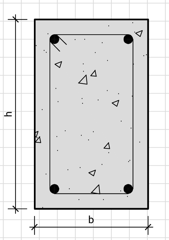
Section Dimensions
L =
mm Effective span of beam
h =
mm Overall depth of beam
b =
mm Width of beam
Figure 1: Geometry
RC Beam Dimensions
Loading
M =
kN·m Design ultimate moment
V =
kN Design ultimate shear force
Mservice = kN·m Service moment for deflection check
Assumed Reinforcement Sizes and Cover
cnom = mm Nominal cover
φmain = mm Main bar diameter
nmain = Number of main bars
φcomp = mm Compression bar diameter (if needed)
ncomp = Number of compression bars (if needed)
φstirrup = mm Stirrup bar diameter
2.0 CALCULATIONS
2.1 Ultimate Limit State (ULS) - Bending
Effective depth to tension steel
d = h − cnom −
φstirrup − φmain/2
d = 450 - 40 - 10 - 20/2 = 380.00 mm
Effective depth to compression steel
dcomp = cnom +
φcomp/2
dcomp = 40 + 16/2 = 48.00 mm
Step 1: Check if compression steel is required
K = M/(b·d²·fcu)
K = 180×10⁶/(250×380²×45) = 0.1109
Kbal = 0.156 (Maximum K for singly reinforced
section)
Compression steel is NOT required (K < Kbal)
K' = 0.1109
Step 2: Calculate lever arm (z)
z = min(d·(0.5 + √(0.25 − K'/0.9)),
0.95·d)
z = min(380×(0.5 + √(0.25 - 0.1109/0.9)),
0.95×380)
z = 361.00 mm
Step 3: Calculate tension reinforcement (As)
As,req =
M/(fy/γs·z)
As,req = 180×10⁶/(500/1.15×361.00) =
1149.62 mm²
Provide main bars (e.g. 3No.T20)
As,prov =
nmain·(φmain/2)²·π
As,prov = 3×(20/2)²×π = 942.48 mm²
Step 4: Calculate compression reinforcement (As')
fcc = 0.45·fcu [Clause
4.3.2.1]
fcc = 0.45×45 = 20.25 MPa
x = d·(0.5 + √(0.25 − Kbal/0.9))
[Depth to neutral axis, using balanced condition]
x = 380×(0.5 + √(0.25 - 0.156/0.9)) = 0.00 mm
fs,comp = min(0.87·fy,comp,
700·(x − dcomp)/x)
fs,comp = min(0.87×500, 700×(0 -
48)/0) = 435.00 MPa
As',req = (K −
Kbal)·b·d²·fcu/(fs,comp·(d
− dcomp))
As',req = (0.1109 -
0.156)×250×380²×45/(435×(380 - 48)) = 0.00 mm²
As,add,req =
As',req·fs,comp/(0.87·fy)
As,add,req = 0.00×435/(0.87×500) = 0.00 mm²
Provide compression bars (e.g. 2No.R16)
As',prov =
ncomp·(φcomp/2)²·π
As',prov = 2×(16/2)²×π =
402.12 mm²
No compression steel required
As',req = 0 mm²
As',prov = 0 mm²
Check if tension reinforcement is sufficient
check_As = FAIL
(As,prov = 942.48
< As,req = 1149.62 mm²)
Check if compression reinforcement is sufficient
check_As' = OK
(Not required)
2.2 Ultimate Limit State (ULS) - Shear Check
Permissible shear stress in concrete
vc = 1
MPa·(0.79·(100·As,prov/(b·d))1/3·max(0.67,
(400/d·1 mm)1/4)·(fcu/25
MPa)1/3)/γc
vc = 1×(0.79×(100×942.48/(250×380))¹ᐟ³·max(0.67,
(400/380)¹ᐟ⁴)·(45/25)¹ᐟ³)/1.25
vc = 0.528
MPa
Maximum shear stress [Clause 3.4.5.2]
vmax = min(0.8·√(fcu/1 MPa), 5)·1 MPa
vmax = min(0.8×√(45/1), 5)×1 = 5.000 MPa
Applied shear stress
v = V/(b·d)
v = 120×10³/(250×380) = 1.263 MPa
Check shear stress
check_vmax = OK
(v = 1.263 ≤ vmax =
5.000 MPa)
check_vc = CHECK
(v = 1.263 > vc = 0.528 MPa)
Shear reinforcement is required
Shear Reinforcement Design
vsv = v − vc
vsv = 1.263 - 0.528 = 0.735 MPa
Vsv,req =
vsv·b·d
Vsv,req = 0.735×250×380 = 69825 N = 69.83 kN
Asv,req =
Vsv,req·γs/(0.87·fy·z)
Asv,req = 69825×1.15/(0.87×500×361.00) = 0.52 mm²/mm = 520 mm²/m
Provide stirrups (e.g. R10@150mm c/c)
Asv,prov = 2·(φstirrup/2)²·π/150
Asv,prov = 2×(10/2)²×π/150 =
2.09 mm²/mm = 2090 mm²/m
check_Asv = OK
(Asv,prov = 2090 ≥
Asv,req = 520 mm²/m)
2.3 Serviceability Limit State (SLS) - Deflection Check
Modification factor for tension reinforcement
Factormod = min(0.55 + (477 MPa −
2·fy·As,req/(3·As,prov))/(120·(0.9 MPa
+ Mservice/(b·d²))), 2)
Factormod = min(0.55 + (477 -
2×500×1149.62/(3×942.48))/(120×(0.9 + 125×10⁶/(250×380²))), 2)
Factormod = 1.000
Allowable span/effective depth ratio
Ratioallow =
Ratiobasic·Factormod
Ratioallow = 26×1.000 = 26.00
Actual span/effective depth ratio
Ratioactual = L/d
Ratioactual = 6000/380 = 15.79
Check deflection
check_deflection = OK
(Ratioactual = 15.79 ≤
Ratioallow = 26.00)
*** OUTPUT SUMMARY ***
Design Summary
Effective depth, d = 380.00
mm
Lever arm, z = 361.00
mm
Required tension steel, As,req = 1149.62 mm²
Provided tension steel, As,prov = 942.48 mm²
Tension reinforcement check: FAIL - Increase reinforcement
Required compression steel (if needed), As',req = 0.00 mm²
Provided compression steel (if needed), As',prov = 0.00 mm²
Compression reinforcement check: OK
Design shear stress, v = 1.263
MPa
Allowable shear stress in concrete, vc = 0.528 MPa
Shear capacity check: CHECK - Shear reinforcement is required
Required shear reinforcement, Asv,req = 520 mm²/m
Provided shear reinforcement, Asv,prov = 2090 mm²/m
Shear reinforcement check: OK
Actual span/depth ratio, Ratioactual = 15.79
Allowable span/depth ratio, Ratioallow = 26.00
Deflection check: OK
RESULTS
DESIGN CHECK - INCREASE TENSION REINFORCEMENT AND PROVIDE SHEAR REINFORCEMENT